Factory Method is a creational design pattern that provides an interface for creating objects in a superclass, but allows subclasses to alter the type of objects that will be created.Abstract FactoryAbstract Factory is a creational design pattern that lets you produce families of related objects without specifying their concrete classes.BuilderBuilder is a creational design pattern that lets you construct complex objects step by step. The pattern allows you to produce different types and representations of an object using the same construction code.PrototypePrototype is a creational design pattern that lets you copy existing objects without making your code dependent on their classes.SingletonSingleton is a creational design pattern that lets you ensure that a class has only one instance, while providing a global access point to this instance.
Adapter
Adapter is a structural design pattern that allows objects with incompatible interfaces to collaborate.
Bridge
Bridge is a structural design pattern that lets you split a large class or a set of closely related classes into two separate hierarchies—abstraction and implementation—which can be developed independently of each other.
Composite
Composite is a structural design pattern that lets you compose objects into tree structures and then work with these structures as if they were individual objects.
Decorator
Decorator is a structural design pattern that lets you attach new behaviors to objects by placing these objects inside special wrapper objects that contain the behaviors.
Facade
Facade is a structural design pattern that provides a simplified interface to a library, a framework, or any other complex set of classes.
Flyweight
Flyweight is a structural design pattern that lets you fit more objects into the available amount of RAM by sharing common parts of state between multiple objects instead of keeping all of the data in each object.
Proxy
Proxy is a structural design pattern that lets you provide a substitute or placeholder for another object. A proxy controls access to the original object, allowing you to perform something either before or after the request gets through to the original object.
Chain of Responsibility
Chain of Responsibility is a behavioral design pattern that lets you pass requests along a chain of handlers. Upon receiving a request, each handler decides either to process the request or to pass it to the next handler in the chain.
Command
Command is a behavioral design pattern that turns a request into a stand-alone object that contains all information about the request. This transformation lets you pass requests as a method arguments, delay or queue a request’s execution, and support undoable operations.
Iterator
Iterator is a behavioral design pattern that lets you traverse elements of a collection without exposing its underlying representation (list, stack, tree, etc.).
Mediator
Mediator is a behavioral design pattern that lets you reduce unorganised dependencies between objects. The pattern restricts direct communications between the objects and forces them to collaborate only via a mediator object.
Memento
Memento is a behavioral design pattern that lets you save and restore the previous state of an object without revealing the details of its implementation.
Observer
Observer is a behavioral design pattern that lets you define a subscription mechanism to notify multiple objects about any events that happen to the object they’re observing.
State
State is a behavioral design pattern that lets an object alter its behavior when its internal state changes. It appears as if the object changed its class.
Strategy
Strategy is a behavioral design pattern that lets you define a family of algorithms, put each of them into a separate class, and make their objects interchangeable.
Template Method
Template Method is a behavioral design pattern that defines the skeleton of an algorithm in the superclass but lets subclasses override specific steps of the algorithm without changing its structure.
Visitor
Visitor is a behavioral design pattern that lets you separate algorithms from the objects on which they operate.

1.
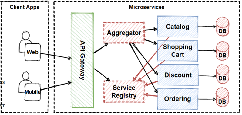
API Gateway Pattern
It is similar to the facade pattern of Object-Oriented Design, so it provides a single entry point to the APIs with encapsulating the underlying system architecture.
In summary, the API gateway locate between the client apps and
the internal microservices. It is working as a reverse proxy and routing
requests from clients to backend services. It is also provide cross-cutting
concerns like authentication, SSL termination, and cache.

You can see the image that is collect client request in single entrypoint and route request to internal microservices. We should careful about this situation, because if we put here a single API Gateway, that means its possible to single-point-of-failure risk in here. If these client applications increase, or adding more logic to business complexity in API Gateway, it would be anti-pattern.
API Gateway service can be growing and evolving based on many
different requirements from the client apps. That’s why the best practices is
splitting the API Gateway in multiple services or multiple smaller API
Gateways. We will see the BFF-Backend-for-Frontend pattern later.
Main Features of API Gateway Pattern
Reverse proxy or gateway routing:
The API Gateway provides reverse proxy to redirect requests to the endpoints of the internal microservices. Usually, It is using layer 7 routing for HTTP requests for request redirections. This routing feature provides to decouple client applications from the internal microservices. So it is separating responsibilities on network layer. Another benefit is abstracting internal operations, API GW provide abstraction over the backend microservices, so even there is changes on backend microservices, it wont be affect to client applications. That means don’t need to update client applications when changing backend services.
Requests aggregation:
API Gateway can aggregate multiple internal microservices into a single client request. With this approach, the client application sends a single request to the API Gateway. After that API Gateway dispatches several requests to the internal microservices and then aggregates the results and sends everything back to the client application in 1 single response. The main benefit of this gateway aggregation pattern is to reduce chattiness communication between the client applications and the backend microservices.
Cross-cutting concerns and gateway offloading:
This is part of gateway offloading pattern features. Since API Gateway handle client request in centralized placed, its best practice to implement cross cutting functionality on the API Gateways.
The cross-cutting functionalities can be;
· Authentication and authorization
· Service discovery integration
· Response caching
· Retry policies, circuit breaker, and QoS
· Rate limiting and throttling
· Load balancing
· Logging, tracing, correlation
· Headers, query strings, and claims transformation
· IP allowlisting
2. CQRS Design Pattern
CQRS stands for Command and Query Responsibility Segregation. Basically this pattern separates read and update operations for a database. Normally, in monolithic applications, most of time we have 1 database and this database should respond both query and update operations.
In example of reading database, if your application required some query that needs to join more than 10 table, this will lock the database due to latency of query computation. Also if we give example of writing database, when performing crud operations we would need to make complex validations and process long business logics, so this will cause to lock database operations.
So reading and writing database has different approaches that we can define different strategy to handle that operation. In order to that CQRS offers to use “separation of concerns” principles and separate reading database and the writing database with 2 database. By this way we can even use different database for reading and writing database types like using no-sql for reading and using relational database for crud operations.
Another consideration is we should understand our application use case behaviors, if our application is mostly reading use cases and not writing so much, we can say our application is read-incentive application.
So we can say that CQRS separates reads and writes into different databases, Commands performs update data, Queries performs read data.In order isolate Commands and Queries, its best practices to separate read and write database with 2 database physically.
Materialized view pattern is good
example to implement reading databases. Because by this way we can avoid
complex joins and mappings with pre defined fine-grained data for query
operations. By this isolation, we can even use different database for reading
and writing database types like using no-sql document database for reading and
using relational database for crud operations.

Instagram Database Architecture
This is so popular on microservices architecture also let me give an example of Instagram architecture. Instagram basically uses two database systems, one is relational database PostgreSQL and the other is no-sql database — Cassandra
How to Sync Databases with CQRS ?
But when we separate read and write databases in 2 different database, the main consideration is sync these two database in a proper way.
So we should sync these 2 databases and keep sync always.
This can be solve by using Event-Driven Architecture. According to Event Driven Architecture, when something update in write database, it will publish an update event with using message broker systems and this will consume by the read database and sync data according to latest changes.
But this solution creates a consistency issue, because since we have implemented async communication with message brokers, the data would not be reflected immediately. This will operates the principle of “eventual consistency”. The read database eventually synchronizes with the write database, and it can be take some time to update read database in the async process.
So if we come back to our read and write databases in CQRS pattern, When starting your design, you can take read database from replicas of write database. By this way we can use different read-only replicas with applying Materialized view pattern can significantly increase query performance. Also when we separated read and write databases, it means we can scale them independently.
Mostly CQRS is using with “Event Sourcing pattern” in Event-Driven Architectures. So after we have learned the CQRS we should learn “Event Sourcing pattern”, because CQRS and “Event Sourcing pattern” is the best practice to use both of them.
3. Materialized View Pattern
The Problem
Let me start with the problem. Think about that we have a use
case that is “add item into shopping cart” use case of our e-commerce
microservices application. You can see illustration in the below image.
According to image we have “Shopping Cart” , “Catalog” and
“Pricing” microservices. And if the user add item into basket, how these
microservices should interact each other ?
· Should Shopping Cart microservice query product data and price information to another microservices with sync calls ? Or
· Are there any other way to handle this problem ? And also
· What if we have transactional use cases that need to interact several services with rollback features ?
In order to solve the questions, We will see patterns and principles for these problems. We will solve this problem with “Materialized View Pattern”.
Materialized View Pattern
So at that stage, Materialized View Pattern is very good option for this problem. Materialized View Pattern is recommend to store its own local copy of data in the microservice.
In our case, shopping cart microservice should have table that contains a denormalized copy of the data which needed from the product and pricing microservices. We can also called this local copy of data as a Read Model. Thats why the name of pattern is Materialized View Pattern.
So Instead of the Shopping Basket microservice querying the Product Catalog and Pricing microservices, it maintains its own local copy of that data. By this way Shopping Cart microservice eliminates the synchronous cross-service calls.
And also this makes Shopping Cart microservice is more resilient, because if Shopping Cart try to call catalog and pricing microservices and if one of the service is down, than the whole operation could be block or rollback. So this pattern broke the direct dependency of other microservices and make faster the response time.
Drawbacks of Materialized View Pattern
But this pattern has also drawback that we have to consider
and make sure when deciding implement this pattern.
The main consideration is How and when the demormalized data
will be updated ?

Because the source of data is other microservices and when the original data changes it should update into SC microservices. There are several way to handle this problem like using message broker systems, when data is changed in the original microservices publish an event and consumes from the subscriber microservice in order to update its denormalized table. Another way can be using a scheduled task, an external trigger, or a manual action to regenerate the table.
4. The Database-per-Service Pattern
One of the core characteristic of the microservices architecture is the loose coupling of services. For that reason every service must have its own databases, it can be polyglot persistence among to microservices.
polyglot persistence
Polyglot Persistence is a fancy term to mean that when storing data, it is best to use multiple data storage technologies, chosen based upon the way data is being used by individual applications or components of a single application. Different kinds of data are best dealt with different data stores. In short, it means picking the right tool for the right use case.
Let’s think about e-commerce application. We will have Product, Ordering and Shopping Cart microservices that each services data in their own databases. Any changes to one database don’t impact other microservices. Database per microservice provides many benefits, especially for evolve rapidly and support massive scale systems.
- Data schema changes made easy without impacting other microservices
- Each database can scale independently
- Microservices Domain data is encapsulated within the service
- If one of the database server is down, this will not affect to other services
Also Polyglot data persistence gives ability to select the best optimized storage needs per microservices.
- The product microservice using NoSQL document database for storing catalog related data which is storing JSON objects to accommodate high-volumes of read operations.
- The shopping cart microservice using a distributed cache that supports its simple, key-value data store.
- The ordering microservice using a relational database to accommodate the rich relational structure of its underlying data.
Because of the ability of massive scale and high availability,
NoSQL databases are getting high popularity and becoming widely use in
enterprise application. Also their schema-less structure give flexibility to
developments on microservices.
5.
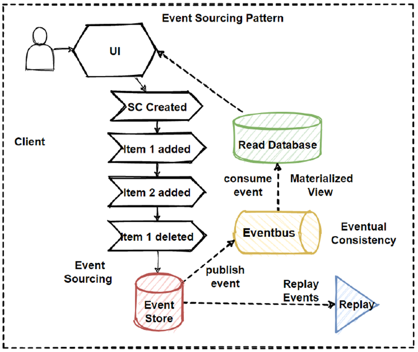
The Event Sourcing Pattern
The Event Sourcing pattern basically provide to accumulate
events and aggregates them into sequence of events in databases.
By this way we can replay at certain point of events. This
pattern is very well using with cqrs and saga patterns.
6.
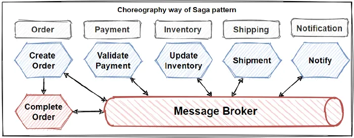
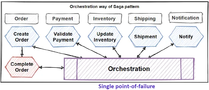
The Saga Pattern
Transaction management in really hard when it comes to
microservices architectures. So in order to implementing transactions between
several microservices and maintaining data consistency, we should follow the
SAGA pattern. Saga pattern has two different approaches:
Choreography — when exchanging events without points of
control
Orchestration — when you have centralized controllers

7.
The Shared Database Anti-Pattern
If you don’t follow The Database-per-Service pattern and use
Shared Database for several microservices, then it is anti-pattern and you
should avoid this approaches.

You can create a single shared database with each service accessing data using local ACID transactions. But it is against to microservices nature and will cause serious problems in the future of applications. At the end of the day, you will face to develop big a few monolithic applications instead of microservices.
Shared database, we will loosing power of microservices
like loose coupling and services independency. Also shared database can block
microservices due to single-point-of-failure.
In order to get benefits of microservices best features we should follow the database-per-service pattern.
8.
Polyglot Persistence
The microservices architecture enables using different kinds
of data storing technologies for different services aka applying polyglot
persistence. Each development team can choose the persistence technology that
suits the needs of their service best.

Martin Fowler has great article about Polyglot Persistence principle and explains that polyglot persistence will come with a cost — but it will come because the benefits are worth it.
When relational databases are used inappropriately, they give damaged on application development. So we should understand how usage is required for microservice, For example If only looked up page elements by ID, and if you had no need for transactions, and no need to share their database, then its not meaningful to use relational database.
A problem like this is much better suited to a key-value
no-sql databases than the corporate relational databases.
9. Circuit Breaker Pattern
The Circuit Breaker design pattern is used to stop the request and response process if a service is not working, as the name suggests.
As an example, assume a consumer sends a request to get data from multiple services. But, one of the services is unavailable due to technical issues. There are mainly two issues you will face now.
· First, because the consumer will be unaware that a particular service is unavailable (failed), so the requests will be sent to that service continuously.
· The second issue is that network resources will be exhausted with low performance and user experience.
You can leverage the Circuit Breaker Design Pattern to avoid such issues. The consumer will use this pattern to invoke a remote service using a proxy. This proxy will behave as a circuit barrier.
When the number of failures reaches a certain threshold, the circuit breaker trips for a defined duration of time.During this timeout period, any requests to the offline server will fail. When that time period is up, the circuit breaker will allow a limited number of tests to pass, and if those requests are successful, the circuit breaker will return to normal operation. If there is a failure, the time out period will start again.

The pattern could have the following three states, such as the followings
Open – request from the Microservice immediately fails, and an exception is returned. The circuit breaker, after a timeout, goes to a Half-Open state.
Closed – routes requests to the Microservice and counts the number of failures. If the number of failures at a certain time exceeds a threshold, it trips to Open State.
Half-Open – only a small number of requests are allowed to pass and invoke the operation. The circuit breaker goes to a Closed state if the requests are successful, and if a request fails, it will go to the Open state.
More on Circuit Breaker:
· Stops cascading of failure to other microservices
· Boosts the architecture’s fault tolerance and resilience
· Helps prevent catastrophic cascading failure across various systems
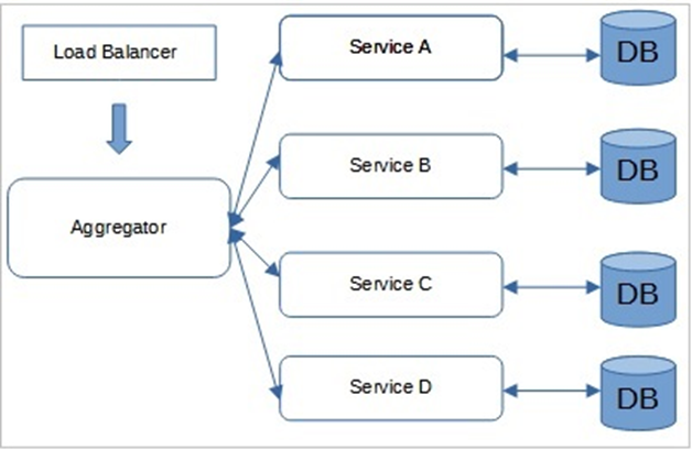
10. Aggregator pattern
Aggregator in Microservices patterns is a basic web page that invokes different services to get the information or achieve the functionality required. Moreover, since the output source is divided on breaking the monolithic architecture to microservices, the pattern proves beneficial when you require an output.
With its unique transaction ID, the Aggregator could collect
the data from every microservice, apply business logic, and publish it as a
REST endpoint. The collected data, later on, could be consumed by the
respective services that require the data collected.
More on Aggregator pattern
· Reduces communication overhead between the client and services
· Enables architecturally and easily understood consolidation of the endpoint of discrete functionality
· Intellectually easy to understand and implement, which lets engineers develop time-to-market solutions rapidly
· X-axis and Z-axis scalability
· Provides microservices with a single access point
11. Chained Microservice Pattern
There will be multiple dependencies of for single services or microservice eg: Sale microservice has dependency products microservice and order microservice. Chained microservice design pattern will help you to provide the consolidated outcome to your request. The request received by a microservice-1, which is then communicating with microservice-2 and it may be communicating with microservice-3. All these services are synchronous calls.
12. Branch Pattern
A microservice may need to get the data from multiple sources including other microservices. Branch microservice pattern is a mix of Aggregator & Chain design patterns and allows simultaneous request/response processing from two or more microservices. The invoked microservice can be chains of microservices. Brach pattern can also be used to invoke different chains of microservices, or a single chain, based your business needs.
13. Strangler Pattern
If we want to use Microservice Architecture in a brownfield project, we need to migrate legacy or existing Monolithic applications to Microservices.
One solution is to use the Strangler pattern. Strangler
pattern means incrementally migrating a Monolithic application to Microservice
Architecture by gradually replacing specific functionality with new
Microservices. Also, new functionalities are only added in Microservices,
bypassing the legacy Monolithic application. A Facade (API Gateway) is then
configured to route the requests between the legacy Monolith and Microservices.
Once the functionality is migrated from the Monolith to Microservices, the
Facade then intercepts the client request and route to the new Microservices.
Once all the legacy monolith's functionalities are migrated, the legacy
Monolithic application is “strangled,” i.e., decommissioned.
The Strangler Application steps are transform, coexist, and eliminate:
Transform — Create a parallel new site
with modern approaches.
Coexist — Leave the existing site where
it is for a time. Redirect from the existing site to the new one so the
functionality is implemented incrementally.
Eliminate — Remove the old functionality
from the existing site.

Pros
· Safe migration of Monolithic application to Microservices.
· The migration and new functionality development can go in parallel.
· The migration process can have its own pace.
Cons
· Sharing Data Store between the existing Monolith and new Microservices becomes challenging.
· Adding a Facade (API Gateway) will increase the system latency.
· End-to-end testing becomes difficult.
When to use Strangler
· Incremental migration of a large Backend Monolithic application to Microservices.
When not to use Strangler
· If the Backend Monolith is small, then wholesale replacement is a better option.
· If the client request to the legacy Monolithic application cannot be intercepted.
14. Bulkhead Pattern
A resilience design pattern called the bulkhead pattern is used to keep systems from collapsing if one component fails. It is named after the compartments that separate the various parts of a ship’s hull so that the ship can still float even if one compartment floods or is damaged.
The Bulkhead Pattern in software architecture divides a system’s various parts or subsystems into isolated groups so that the other groups can continue to operate normally even if one group fails or becomes overburdened. In essence, the pattern makes sure that every group of components has access to exclusive resources and is not hampered by the failures or traffic of other groups.
Benefits
- Better fault isolation
- Increased availability
- Better scalability
15. Sidecar Pattern
The sidecar design pattern is a software architecture pattern in which an application is split into two separate processes: a primary application process and a secondary process called the "sidecar". The sidecar process runs alongside the primary application process and provides additional functionality that is not directly related to the core functionality of the primary process.
The sidecar process typically runs in its own container and can be used to perform tasks such as logging, monitoring, and handling network traffic. The primary application communicates with the sidecar process through a local interface or network protocol, such as HTTP or gRPC.
One of the main advantages of the sidecar design pattern is that it allows for modular design, making it easier to add and remove functionality from an application without affecting the core functionality. Additionally, the sidecar can be implemented in a different language or technology stack than the primary application, providing flexibility in technology choices.
One common use case for the sidecar design pattern is in microservice architectures, where multiple independent services are deployed in separate containers and communicate with each other using APIs. In this context, the sidecar can be used to provide additional functionality, such as service discovery or load balancing.
Overall, the sidecar design pattern provides a flexible and scalable way to extend the functionality of an application without affecting its core functionality.
16. Proxy Pattern
The proxy microservice design pattern is a software architecture pattern that involves using a separate microservice to act as an intermediary between clients and other microservices. This intermediary microservice, known as the proxy or gateway, is responsible for handling incoming requests, forwarding them to the appropriate microservice, and returning the response to the client.
One of the main benefits of using the proxy microservice design pattern is that it helps to decouple clients from individual microservices, making it easier to make changes to the underlying microservices without impacting clients. This is achieved by providing a single point of entry for clients to access multiple microservices, with the proxy microservice handling all the necessary routing and orchestration.
In addition, the proxy microservice can also provide additional functionality such as authentication, rate limiting, caching, and logging, which can be useful in ensuring the security, reliability, and performance of the microservices architecture.
Another advantage of the proxy microservice design pattern is that it enables the use of different communication protocols and message formats between the proxy and the underlying microservices, allowing for greater flexibility in technology choices.
Overall, the proxy microservice design pattern is a useful approach to building scalable and flexible microservices architectures, providing a way to decouple clients from individual microservices and adding additional functionality to improve performance, reliability, and security.
17. Log Aggregation
The log aggregation design pattern is a software architecture pattern that involves collecting and centralizing logs from multiple sources into a single, centralized location. This can be useful in large-scale distributed systems where logs are generated by many different services and components.
The main purpose of the log aggregation design pattern is to simplify the process of monitoring and troubleshooting complex distributed systems. By centralizing logs into a single location, it becomes easier to search, analyze, and correlate logs from different sources, enabling developers and operators to quickly identify and diagnose issues.
There are several different approaches to implementing the log aggregation design pattern. One common approach is to use a dedicated log aggregation service, such as Elasticsearch, Logstash, and Kibana (ELK stack) or Splunk. These services can collect logs from different sources and provide powerful search, filtering, and analysis capabilities.
Another approach is to use a log forwarding agent, such as Fluentd or Logstash, to collect and forward logs to a centralized location. This approach can be more lightweight and flexible, but may require additional configuration and maintenance.
Overall, the log aggregation design pattern is a valuable tool for managing the complexity of large-scale distributed systems. By centralizing logs, it becomes easier to monitor, troubleshoot, and optimize the performance of complex systems, improving overall system reliability and availability.
18. Performance Metrics
The performance metrics design pattern is a software architecture pattern that involves collecting and analyzing performance data from a system to improve its performance, scalability, and reliability. This pattern is commonly used in large-scale distributed systems where performance optimization is critical.
The main purpose of the performance metrics design pattern is to collect and analyze metrics related to the performance of different components of the system, such as CPU usage, memory usage, disk I/O, network I/O, and response times. These metrics can be used to identify bottlenecks and optimize the system for better performance.
There are several approaches to implementing the performance metrics design pattern. One common approach is to use a monitoring tool or service, such as Prometheus or Datadog, to collect and store performance metrics. These tools can also provide powerful visualization and alerting capabilities, making it easy to identify and diagnose performance issues in real-time.
Another approach is to use profiling tools, such as VisualVM or YourKit, to analyze the performance of individual components of the system. These tools can provide detailed insights into the performance characteristics of specific components, enabling developers to identify and fix performance bottlenecks.
Overall, the performance metrics design pattern is an essential tool for managing the performance of complex distributed systems. By collecting and analyzing performance metrics, developers can identify and diagnose performance issues, optimize the system for better performance, and ensure its reliability and scalability.
19. Distributed Tracing
Distributed tracing is a technique used in software engineering to debug and optimize complex distributed systems. It involves tracing a request as it propagates through a distributed system, collecting data at each step, and then aggregating that data to provide a complete picture of the request's path through the system.
Here are the key components of a distributed tracing design pattern:
- Instrumentation: The first step is to instrument the application code with tracing hooks. These hooks allow you to trace the flow of requests through the system and collect data at various points.
- Trace Context: Once the tracing hooks are in place, you need to establish a trace context that is shared across all the services involved in processing a particular request. This context typically includes a unique trace ID and various other metadata.
- Trace Propagation: As a request flows through the system, the trace context is propagated from one service to the next. Each service can add its own metadata to the trace context, allowing you to collect detailed information about the request's path through the system.
- Data Collection: As the trace context is propagated, each service collects data about the request, including timing information, error messages, and other relevant metadata. This data is then sent to a centralized tracing system for aggregation and analysis.
- Analysis and Visualization: The final step is to analyze and visualize the collected data to gain insights into the performance and behavior of the distributed system. This analysis can be used to identify bottlenecks, optimize performance, and diagnose issues in the system.
Overall, a distributed tracing design pattern is essential for gaining visibility into the behavior of complex distributed systems. By tracing the flow of requests through the system and collecting data at each step, you can gain insights that would be impossible to obtain through other means.
20. Health Check
When microservice architecture has been implemented, there is a chance that a service might be up but not able to handle transactions. Each service needs to have an endpoint which can be used to check the health of the application, such as /health. This API should check the status of the host, the connection to other services/infrastructure, and any specific logic.
21. External Configuration
The External Configuration design pattern is a software design pattern used to manage configuration settings for an application or system.
In this pattern, the configuration settings are stored externally in a configuration file, database, or some other form of external storage. The application reads the configuration settings from this external source at runtime, allowing for greater flexibility and easier maintenance of the configuration settings.
The advantages of using the External Configuration design pattern include:
- Centralized management: Storing configuration settings externally allows for centralized management, making it easier to update and maintain configuration settings across multiple instances of an application or system.
- Flexibility: The ability to update configuration settings without having to modify the application's code provides greater flexibility and reduces the need for recompilation and redeployment.
- Security: Storing sensitive configuration settings externally can help to improve security by reducing the risk of accidental exposure of sensitive information.
Some common examples of external configuration sources include XML files, JSON files, INI files, properties files, and databases.
22. Service Discovery Pattern
The Service Discovery pattern is a software architecture pattern that is commonly used in distributed systems to dynamically discover and locate services at runtime. In a distributed system, services can be spread across multiple nodes or instances, making it challenging to manage and access them. The Service Discovery pattern provides a solution to this problem by providing a mechanism for services to register themselves with a central registry, and for other services to query this registry to discover available services.
In the Service Discovery pattern, a central registry, also known as a Service Registry, is used to store information about available services, such as their network address, port, and protocol. When a service is started, it registers itself with the registry, providing its identifying information. Other services that need to use this service can then query the registry to discover its location and other details. This allows services to be decoupled from each other, as they can discover and communicate with each other dynamically at runtime.
There are several different implementations of the Service Discovery pattern, including DNS-based discovery, client-side discovery, and server-side discovery. DNS-based discovery involves using DNS records to store information about services, while client-side discovery involves having each client query the registry directly to discover available services. Server-side discovery, on the other hand, involves using a load balancer or proxy to route requests to available services, based on information stored in the Service Registry.
Overall, the Service Discovery pattern is a powerful tool for managing and accessing services in distributed systems, allowing services to be located and accessed dynamically, without the need for hard-coded configuration or manual intervention.
There are several benefits to using the Service Discovery Pattern:
- Scalability: As the number of services in a distributed system increases, the Service Discovery Pattern makes it easier to scale the system by automating the process of locating and connecting to services.
- Flexibility: The Service Discovery Pattern provides greater flexibility by allowing services to be added or removed dynamically, without requiring changes to the client code.
- Resilience: The Service Discovery Pattern helps to improve the resilience of a distributed system by allowing services to be automatically re-routed or reconnected if they fail or are moved to a different location.

23. Blue-Green Deployment Pattern
With microservice architecture, one application can have many
microservices. If we stop all the services then deploy an enhanced version, the
downtime will be huge and can impact the business. Also, the rollback will be a
nightmare. Blue-Green Deployment Pattern avoid this.

The blue-green deployment strategy can be implemented to reduce or remove downtime. It achieves this by running two identical production environments, Blue and Green. Let’s assume Green is the existing live instance and Blue is the new version of the application. At any time, only one of the environments is live, with the live environment serving all production traffic. All cloud platforms provide options for implementing a blue-green deployment.
24.
Consumer-Driven Contract Testing
In Microservice Architecture, there are many Microservices often developed by separate teams. These microservices work together to fulfill a business requirement (e.g., customer request) and communicate with each other Synchronously or Asynchronously. Integration testing of a Consumer Microservice is challenging. Usually, TestDouble is used in such scenarios for a faster and cheaper test run. But TestDouble often does not represent the real Provider Microservice. Also, if the Provider Microservice changes its API or Message, then TestDouble fails to acknowledge that. The other option is to make end-to-end testing. While end-to-end testing is mandatory before production, it is brittle, slow, expensive, and is no replacement for Integration testing (Test Pyramid).
Consumer-Driven contract testing can help us in this regard. Here, the Consumer Microservice owner team write a test suite containing its Request and expected Response (for Synchronous communication) or expected messages (for Asynchronous communication) for a particular Provider Microservice.
Consumer-Driven Contract (CDC) Testing is a testing methodology that is focused on ensuring the compatibility and correctness of services in a distributed system. The concept of CDC testing has emerged as a response to the increasing popularity of microservices architecture, which is highly modular and distributed.
In a microservices architecture, services are developed and deployed independently. Each service has its own API, which is consumed by other services. However, when services change their API, it can impact the other services that rely on them. CDC testing helps to mitigate this risk by providing a way for each service to define its own contract and to test against that contract.
CDC testing is driven by the consumer of the service, rather than the provider. The consumer defines the contract that the service must adhere to, and then tests the service against that contract. This approach ensures that any changes made to the service will not break the contract, and will not impact the consumer.
The CDC testing process involves the following steps:
- The consumer defines the contract: The consumer of the service defines the contract that the service must adhere to. This contract describes the expected input and output of the service, as well as any other requirements.
- The provider implements the contract: The service provider implements the contract defined by the consumer.
- The consumer tests the service: The consumer tests the service against the contract. If the service passes the test, it is considered compatible with the consumer.
- The provider deploys the service: The service provider deploys the service to production, knowing that it is compatible with the consumer.
CDC testing has many benefits, including:
- Improved reliability: By testing services against contracts, CDC testing ensures that services are reliable and adhere to a consistent set of requirements.
- Faster development: CDC testing enables services to be developed and deployed faster, since each service can be developed and tested independently.
- Reduced risk: CDC testing reduces the risk of service changes impacting other services in the system.
Overall, CDC testing is a valuable testing methodology for distributed systems, particularly those based on microservices architecture.
25.
Backends for Frontends (BFF)
In modern business application developments and especially in Microservice Architecture, the Frontend and the Backend applications are decoupled and separate Services. They are connected via API or GraphQL. If the application also has a Mobile App client, then using the same backend Microservice for both the Web and the Mobile client becomes problematic. The Mobile client's API requirements are usually different from Web client as they have different screen size, display, performance, energy source, and network bandwidth.
Backends for Frontends pattern could be used in scenarios
where each UI gets a separate backend customized for the specific UI. It also
provides other advantages, like acting as a Facade for downstream
Microservices, thus reducing the chatty communication between the UI and
downstream Microservices. Also, in a highly secured scenario where downstream
Microservices are deployed in a DMZ network, the BFF’s are used to provide
higher security.

Pros
· Separation of Concern between the BFF’s. We can optimize them for a specific UI.
· Provide higher security.
· Provide less chatty communication between the UI’s and downstream Microservices.
Cons
· Code duplication among BFF’s.
· The proliferation of BFF’s in case many other UI’s are used (e.g., Smart TV, Web, Mobile, Desktop).
· Need careful design and implementation as BFF’s should not contain any business logic and should only contain client-specific logic and behavior.
When to use Backends for Frontends
· If the application has multiple UIs with different API requirements.
· If an extra layer is needed between the UI and Downstream Microservices for Security reasons.
· If Micro-frontends are used in UI development.
When not to use Backends for Frontends
· If the application has multiple UI, but they consume the same API.
· If Core Microservices are not deployed in DMZ.
26.
Asynchronous Message-Based
Communication
In asynchronous message-based communication, the sender of a message does not wait for an immediate response from the receiver. Instead, the sender sends the message and can continue to work on other tasks while waiting for a response. The receiver of the message can handle the message whenever it is convenient for it to do so.
The messages themselves are usually structured as data objects, containing all the necessary information for the receiver to understand and process the message. The message can contain simple data types like strings, numbers, or more complex data structures like JSON or XML.
One of the benefits of asynchronous message-based communication is that it allows for greater flexibility and scalability in distributed systems. Components can be added or removed from the system without disrupting the overall functionality of the system. Additionally, components can operate independently of each other, without the need for complex synchronization mechanisms.
Another benefit is the ability to handle large volumes of data in a distributed system. Asynchronous message-based communication allows for the decoupling of sender and receiver, which means that the sender can continue to work on other tasks while the receiver is processing the message. This allows for greater efficiency and throughput in systems that need to handle large volumes of data.
Some examples of messaging technologies used for asynchronous message-based communication include AMQP (Advanced Message Queuing Protocol), Kafka, and RabbitMQ. These messaging technologies provide features such as message queues, topics, and routing, which allow for more sophisticated message handling and delivery guarantees.
Overall, asynchronous message-based communication is a powerful pattern for building distributed systems that are flexible, scalable, and efficient in handling large volumes of data.
27.
Decomposition
The Decomposition pattern is often used in object-oriented programming to create a system that is modular, flexible, and maintainable. It involves dividing a larger problem into smaller subproblems, each of which can be solved independently. Once the smaller subproblems have been solved, they can be combined to solve the larger problem.
The Decomposition pattern has several benefits, including:
- Improved Modularity: By breaking down a complex problem into smaller subproblems, the resulting system is more modular and easier to understand and maintain.
- Increased Flexibility: The modular nature of the system allows for greater flexibility in making changes or adding new features.
- Better Reusability: The smaller subproblems can be reused in other parts of the system, reducing duplication of effort and improving overall code quality.
- Enhanced Testing: Testing can be performed on individual subproblems, making it easier to identify and fix bugs.
In summary, the Decomposition pattern is a useful tool for designing complex systems that are modular, flexible, and maintainable. By breaking down a larger problem into smaller subproblems, each subproblem can be solved independently, resulting in a more efficient and effective overall solution.
Decomposition Pattern — Decompose by Business Capability
Decomposition by business capability is a pattern used to break down a complex system or organization into smaller, more manageable parts based on the business capabilities required to achieve its goals.
A business capability refers to a particular set of activities, processes, and resources required to achieve a specific business outcome. By decomposing a system or organization into its various business capabilities, you can better understand the different parts that make up the whole and how they contribute to the overall success of the organization.
To apply this pattern, you can follow these steps:
- Identify the business capabilities required to achieve the organization's goals. This can be done by analyzing the organization's strategic objectives and determining the specific activities and processes needed to achieve them.
- Break down the system or organization into smaller parts based on the identified business capabilities. For example, if the organization's goals include delivering products to customers, you might identify business capabilities such as product design, manufacturing, and distribution.
- Define the relationships between the different business capabilities. This can help you understand how they work together to achieve the organization's goals. For example, product design might be dependent on customer research and feedback, while manufacturing might depend on the availability of raw materials.
- Determine the key performance indicators (KPIs) for each business capability. This can help you measure the performance of each capability and identify areas for improvement. For example, KPIs for the manufacturing capability might include production efficiency, quality control, and on-time delivery.
By decomposing a system or organization into its various business capabilities, you can gain a better understanding of its structure and how it functions. This can help you identify areas for improvement and optimize the organization's performance.
Decomposition Pattern — Decompose by Subdomain
Decomposition by subdomain is a pattern used to break down a complex system or organization into smaller, more manageable parts based on the different subdomains or functional areas that it comprises.
A subdomain refers to a specific area of functionality within a system or organization, such as accounting, marketing, or customer service. By decomposing a system or organization into its different subdomains, you can better understand the different parts that make up the whole and how they work together to achieve the organization's goals.
To apply this pattern, you can follow these steps:
- Identify the different subdomains or functional areas that make up the system or organization. This can be done by analyzing the organization's structure and identifying the different departments or teams that are responsible for different areas of functionality.
- Break down the system or organization into smaller parts based on the identified subdomains. For example, if the organization includes an accounting department, a marketing department, and a customer service department, you might decompose the organization into these three subdomains.
- Define the relationships between the different subdomains. This can help you understand how they work together to achieve the organization's goals. For example, the marketing department might be responsible for generating leads, which the customer service department can then convert into sales.
- Determine the key performance indicators (KPIs) for each subdomain. This can help you measure the performance of each subdomain and identify areas for improvement. For example, KPIs for the accounting subdomain might include financial accuracy and timeliness of reporting.
By decomposing a system or organization into its different subdomains, you can gain a better understanding of its structure and how it functions. This can help you identify areas for improvement and optimize the organization's performance. Additionally, this pattern can help facilitate communication and collaboration between different departments or teams within the organization.
28. Domain-Driven Design
Domain-Driven Design (DDD) is an approach to software development that focuses on understanding and modeling the core business domain of a software application. The goal of DDD is to create software that accurately reflects the real-world domain it is designed to support, and that is well-aligned with the needs of the business.
DDD emphasizes collaboration between technical experts and domain experts (such as business analysts, product owners, or subject matter experts) in order to develop a shared understanding of the domain and to create a shared language for discussing it. This collaboration is intended to ensure that the software design is driven by business needs, rather than being overly influenced by technical concerns.
DDD also includes a number of technical patterns and practices that support the modeling of complex domains. These patterns and practices include:
- Bounded contexts: Dividing a system into smaller, more focused domains, each with its own language, models, and boundaries. This allows for greater clarity and separation of concerns within the overall system.
- Ubiquitous language: Using a common language across all parts of the system, from code to documentation to conversations between domain experts and technical experts. This helps to ensure that everyone involved in the development process is using the same terminology and concepts.
- Entities and value objects: Modeling domain objects as either entities (objects with unique identities that persist over time) or value objects (objects that have no identity and are defined by their attributes). This helps to clarify the relationships between objects in the domain and to ensure that objects are modeled in a way that accurately reflects their real-world characteristics.
- Domain events: Capturing important changes or events in the domain as "domain events", which can then be used to trigger other actions or updates within the system. This helps to ensure that the system is responsive to changes in the domain and can adapt to evolving business needs.
DDD can be a powerful approach to software development, particularly for complex applications that involve multiple domains and business processes. However, it can also be challenging to implement, and requires a high degree of collaboration and communication between technical and domain experts.
29. A Bounded Context is equal to A Microservice?
A Bounded Context and a Microservice are related concepts but they are not exactly the same thing.
A Bounded Context is a concept from Domain-Driven Design (DDD) which defines the scope and boundaries of a particular domain model. It is a way of breaking down a complex business domain into smaller, more manageable parts. A Bounded Context is defined by a specific set of business requirements, and all entities, services, and operations within that context are related to those requirements. It is a way of organizing code and data in a way that makes sense to the business.
On the other hand, a Microservice is a software architecture pattern that involves breaking down a large, monolithic application into smaller, independent services. Each service is designed to perform a specific function, and communicates with other services through APIs. A Microservice is a self-contained component that can be developed, deployed, and scaled independently of other services. It is a way of decomposing a large, complex application into smaller, more manageable parts.
While a Microservice can be implemented within a Bounded Context, it is not the same thing. A Bounded Context can contain multiple Microservices that work together to fulfill the business requirements of that context. Similarly, a Microservice can span multiple Bounded Contexts if it provides functionality that is shared across multiple domains.
In summary, a Bounded Context is a way of organizing code and data within a specific domain, while a Microservice is a way of breaking down a large, monolithic application into smaller, independent services. While they are related concepts, they are not interchangeable, and can be used in combination to create a flexible and scalable software architecture.
30.
Database Sharding Pattern
The database sharding pattern is a database architecture pattern that involves splitting a large database into smaller, more manageable units called shards. Each shard contains a subset of the data, and the shards are distributed across multiple servers.
The purpose of sharding is to improve performance and scalability by allowing the database to handle more data and requests than a single server could handle. Sharding can also improve fault tolerance, as a failure in one shard does not affect the availability of other shards.
The following are some common approaches to implementing database sharding:
- Horizontal sharding: This approach involves partitioning the data by rows, where each shard contains a subset of rows. This is typically used for large-scale databases where the data is partitioned based on a specific attribute or key, such as customer ID or geographic location.
- Vertical sharding: This approach involves partitioning the data by columns, where each shard contains a subset of columns. This is typically used for databases where the data is partitioned based on the type of data, such as storing less frequently accessed columns on separate shards.
- Hybrid sharding: This approach combines both horizontal and vertical sharding, where the data is partitioned by both rows and columns. This allows for more granular control over how the data is distributed across the shards.
Implementing database sharding requires careful planning and consideration of factors such as data distribution, query routing, and fault tolerance. However, when done correctly, sharding can significantly improve database performance and scalability.

Tinder — Database Sharding Pattern
If we give an example, Tinder is very good example of database sharding pattern. Tinder is one of the most popular apps in the world for those who want to meet new people. It allows you to match and meet other people who use the application near you (around 160km) based on location.
Tinder segments users based on their location. This is called GeoSharding, that is, location-based database sharding.Cassandra no-sql databases which is automatically includes database sharding and scaling features.
Apache Cassandra is a highly scalable, high-performance
distributed database designed to handle large amounts of data across many
different located servers, providing high availability with no single point of
failure. It is a type of NoSQL database.
31. Service Aggregator Pattern
In order to minimize service-to-service communications, we can apply Service Aggregator Pattern.
Basically, The Service aggregator design pattern is receives a request from the client or API Gateways, and than dispatches requests of multiple internal backend microservices, and than combines the results and responds back to the initiating request in 1 response structure.
By Service Aggregator Pattern implementation, we can reduces
chattiness and communication overhead between the client and microservices.

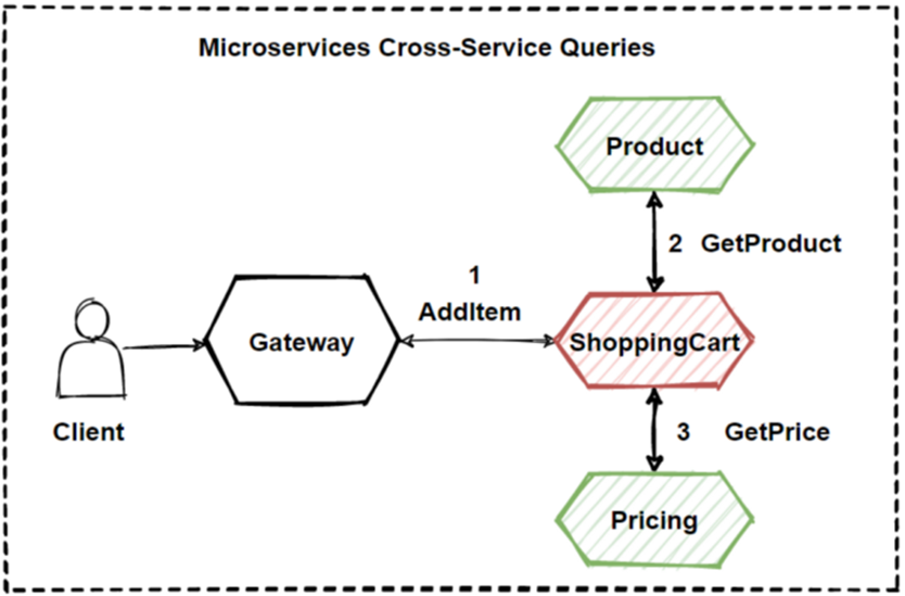
Lets see the image, You can find here is AddItem Aggregator Microservice which basically orchestrates the AddItem into Shopping Cart operation. And it aggregates request to several back-end microservices which's are Product, Shopping Cart and Pricing.
So we can say that this pattern isolates the underlying
AddItem operation that makes calls to multiple back-end microservices,
centralizing its logic into a AddItem Aggregator Microservice.
As you can see that we have applied Service Aggregator Pattern
— Service Registry Pattern for our e-commerce architecture.
32. The Outbox Pattern
The Outbox Pattern is a software design pattern used in distributed systems to reliably publish events or messages to one or more downstream systems, even in the event of failures or downtime. The pattern helps ensure that data is not lost in transit, while also improving the overall resilience and scalability of the system.
In the Outbox Pattern, events or messages are written to a local database table, known as the Outbox. This table acts as a buffer between the application and the downstream systems, allowing the application to continue processing without waiting for acknowledgement from the downstream systems. The Outbox table can be designed to include information such as the event payload, metadata, and a timestamp.
A background process, known as the Outbox Processor, is responsible for reading the events from the Outbox table and publishing them to the downstream systems. The Outbox Processor reads the events in batches, ensuring that the number of events being processed is within acceptable limits. Once an event has been successfully published, it is marked as processed in the Outbox table and can be deleted.
One of the main benefits of the Outbox Pattern is that it allows the application to continue processing without being blocked by slow or unreliable downstream systems. In addition, the pattern ensures that events are not lost in the event of network failures or downtime, as they are stored locally in the Outbox table. Furthermore, the Outbox Processor can be designed to be fault-tolerant, allowing it to retry failed events or handle errors in a graceful manner.
Overall, the Outbox Pattern is a powerful tool for building reliable and scalable distributed systems. It provides a way to decouple the application from the downstream systems, while also ensuring that events are delivered reliably and without loss.

33.
Service Registry Pattern
In the Service Registry Pattern, a central registry, also known as a Service Registry, is used to store information about available services, such as their network address, port, and protocol. When a service is started, it registers itself with the registry, providing its identifying information. Other services that need to use this service can then query the registry to discover its location and other details. This allows services to be decoupled from each other, as they can discover and communicate with each other dynamically at runtime.
The Service Registry Pattern can be implemented using various technologies, such as DNS, RESTful APIs, and message brokers. The most commonly used implementation of this pattern is the client-side discovery approach, where each client is responsible for discovering the available services by querying the Service Registry directly.
One of the primary benefits of the Service Registry Pattern is that it allows for the dynamic and automatic discovery of services, making it easier to develop and maintain distributed systems. It also provides a centralized and flexible approach to service management, enabling easy addition, removal, or updating of services. Additionally, the Service Registry Pattern can improve the overall reliability and scalability of distributed systems by facilitating load balancing and failover.
However, the Service Registry Pattern can also introduce new challenges such as the need for high availability of the Service Registry, synchronization issues, and the need to handle service registration and deregistration events gracefully. Nevertheless, with proper implementation and management, the Service Registry Pattern can be a powerful tool for building and managing distributed systems.

34. Difference between Service Discovery Pattern and Service Registry Pattern?
Both Service Discovery Pattern and Service Registry Pattern are used in microservices architecture to facilitate communication between services, but they differ in their approach to managing service information.
The Service Registry Pattern involves having a central registry that maintains a list of all available services and their metadata. Services are registered with the registry when they start up, and deregistered when they shut down. Clients can query the registry to discover the available services and their locations, and use this information to make requests to the services. Some popular service registry tools include Netflix Eureka, HashiCorp Consul, and ZooKeeper.
On the other hand, the Service Discovery Pattern involves having services discover each other dynamically at runtime, without the need for a central registry. Services can broadcast their availability and location through a messaging system or protocol, and other services can subscribe to this information and use it to discover the available services. Some popular service discovery tools include Kubernetes, Istio, and Linkerd.
The main difference between these two patterns is that the Service Registry Pattern relies on a central registry for service discovery, while the Service Discovery Pattern uses a decentralized approach. The Service Registry Pattern provides a more centralized way of managing service information, but may introduce a single point of failure if the registry goes down. The Service Discovery Pattern provides a more flexible and resilient approach, but may require more overhead to implement and maintain.
Ultimately, the choice between these two patterns depends on the specific requirements and constraints of the microservices architecture being designed.
35.
Fan-out is a messaging pattern
The fan-out messaging pattern is a messaging pattern used in distributed systems where a single message is sent from a source to multiple recipients, also known as subscribers. In this pattern, the message is broadcasted to all subscribers, and each subscriber receives a copy of the message.
This pattern is commonly used in publish-subscribe systems, where the publisher sends messages to a topic or channel, and the subscribers receive the messages from that topic or channel. The fan-out pattern ensures that each subscriber receives the message independently and at the same time, without any dependency on other subscribers or the publisher.
One of the advantages of using the fan-out messaging pattern is that it enables the scalability of the messaging system. With this pattern, the messaging system can efficiently handle a large number of subscribers without affecting the performance or adding significant overhead to the system.
However, it is important to note that the fan-out pattern can lead to increased network traffic and processing load on the subscriber side, as each subscriber receives a copy of the message. Therefore, it is important to design the system carefully and use appropriate strategies to optimize the performance and minimize the impact on the system.
The fan-out pattern is commonly used in messaging systems like RabbitMQ, Apache Kafka, and Amazon SNS to broadcast updates, events, or notifications to multiple consumers or microservices that need to react to them in real-time. It's often used in scenarios where a large number of subscribers need to receive the same message without adding any additional load on the publisher.

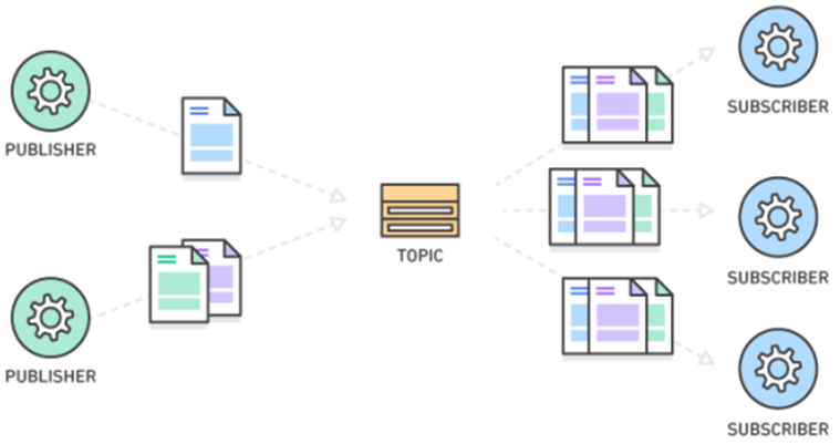
The Publish-Subscribe messaging pattern, also known as pub/sub, is a messaging pattern that involves multiple publishers and subscribers. In this pattern, publishers send messages to a central message broker, which then distributes these messages to all subscribed consumers or subscribers who have expressed an interest in receiving those messages.
The pattern has the following key elements:
- Publisher: a component that sends messages to the message broker
- Subscriber: a component that receives messages from the message broker
- Message broker: a central component that receives messages from publishers and distributes them to subscribers
The pattern is used to decouple the publishers and subscribers from each other, allowing them to operate independently. Publishers do not need to know anything about subscribers, and subscribers do not need to know anything about publishers. The message broker acts as an intermediary between the two, providing a scalable and flexible way to distribute messages.
The pub/sub pattern can be implemented in different ways, depending on the requirements of the system. Some popular implementations include:
- Topic-based pub/sub: messages are sent to a topic or channel, and subscribers subscribe to specific topics of interest. The message broker then distributes messages to subscribers based on their subscriptions.
- Fan-out pub/sub: messages are sent to a message queue, and the message broker distributes messages to all subscribers who are interested in receiving them. This approach can be useful for real-time updates or notifications.
Some advantages of the pub/sub pattern include:
- Scalability: because the message broker handles the distribution of messages, the pattern can easily scale to handle large numbers of publishers and subscribers.
- Decoupling: the pattern allows publishers and subscribers to operate independently, which can make it easier to maintain and update the system over time.
- Flexibility: the pattern can be adapted to different use cases and requirements by using different implementations.
Some disadvantages of the pub/sub pattern include:
- Complexity: the pattern can be more complex to implement than other messaging patterns, especially when using more advanced features such as filtering or routing.
- Latency: because messages are sent through a message broker, there can be some latency or delay in delivering messages to subscribers.
- Reliability: the pattern relies on the message broker to reliably distribute messages, which can be a single point of failure.
37. Topic-Queue Chaining
The topic-queue chaining pattern is a messaging pattern that combines the features of both the publish-subscribe and point-to-point messaging patterns. This pattern allows messages to be routed to one or more specific consumers while also being broadcast to a group of subscribers.
In this pattern, messages are published to a topic, which is a logical channel that can be subscribed to by multiple consumers. The messages are then routed to a queue, which is a storage area that holds messages until they can be consumed by a specific consumer.
The topic-queue chaining pattern works by creating a chain of messaging components, with each component responsible for a specific task. The first component in the chain is a publisher, which sends messages to a topic. The second component is a message router, which receives messages from the topic and routes them to one or more queues based on their content.
The third component is a set of message queues, which hold messages until they can be consumed by a specific consumer. The final component is a set of message consumers, which receive messages from the queues and process them.
This pattern allows for a flexible and scalable messaging system, where messages can be delivered to a specific consumer or a group of subscribers. It is often used in distributed systems, where messages need to be delivered to multiple consumers, but some messages need to be processed by a specific consumer.
One potential drawback of this pattern is that it can be more complex than other messaging patterns, due to the need for multiple messaging components and the potential for message routing issues. However, when implemented correctly, the topic-queue chaining pattern can provide a highly flexible and scalable messaging system.

38. Load Balancing Pattern
The Load Balancing pattern is a design pattern used to distribute workloads across multiple resources or servers, in order to improve performance, scalability, and availability. This pattern can be used in a variety of applications and systems, including web servers, database servers, and distributed systems.The Load Balancing pattern involves the use of a load balancer, which is a component that sits between the clients and the servers, and distributes incoming requests or workloads across multiple resources or servers based on a specific algorithm or set of rules.
The load balancer can be configured to use different algorithms to distribute workloads, such as round-robin, least connections, or IP hash. The choice of algorithm depends on the specific requirements of the system and the workload being balanced.
One common implementation of the load balancing pattern is the use of a round-robin algorithm, where incoming requests are evenly distributed among a group of servers in a circular order. Another popular approach is to use a weighted algorithm, where each server is assigned a weight based on its capacity or processing power.
Some advantages of the Load Balancing pattern include:
- Improved performance: by distributing workloads across multiple servers, the Load Balancing pattern can help to reduce response times and increase throughput, as each server can handle a smaller workload.
- Scalability: the Load Balancing pattern can be used to scale up or down resources or servers as needed, without impacting the overall system.
- Availability: by distributing workloads across multiple servers, the Load Balancing pattern can help to improve availability and reduce the impact of failures or downtime on the system.
- Complexity: implementing and configuring a load balancer can be complex, and may require specialized knowledge and expertise.
- Single point of failure: the load balancer can be a single point of failure, and needs to be designed and configured to be highly available and fault-tolerant.
- Cost: implementing a load balancing solution can be costly, as it may require additional hardware and software.
39. Retry Pattern
The retry pattern is a design pattern used to handle errors and failures in distributed systems by automatically retrying failed operations. In this pattern, when an operation fails, the system automatically retries the operation after a specified delay or based on certain conditions.
The retry pattern is commonly used to handle transient errors, which are errors that occur due to temporary conditions such as network congestion, timeouts, or service outages. By automatically retrying failed operations, the system can often recover from these errors without requiring user intervention or causing significant downtime.
The retry pattern can be implemented in different ways, such as:
- Simple Retry: In this implementation, the system retries the operation a fixed number of times with a fixed delay between retries. If the operation still fails after the last retry, the system reports the error.
- Exponential Backoff Retry: In this implementation, the delay between retries increases exponentially after each retry. This approach is often used to avoid overwhelming the system with retry attempts and to give the system time to recover from transient errors.
- Circuit Breaker Retry: In this implementation, the system monitors the success and failure rates of operations and switches to a "circuit open" state if the failure rate exceeds a certain threshold. In this state, the system stops retrying the operation and returns an error immediately. The system then waits for a specified period before switching back to a "circuit closed" state and allowing retries.
The retry pattern can provide several benefits, including improved system reliability, reduced downtime, and improved user experience. By automatically retrying failed operations, the system can recover from transient errors and continue to provide service without requiring user intervention or causing significant downtime. However, it is important to implement the retry pattern correctly to avoid creating new errors or overloading the system with retry attempts.
40.
CAP Theorem
How to Choose a Database for Microservices ?
This really important question and there are several way to understand your database requirements as per microservices.
There are several key points when we decide databases. First of all is the consider the “consistency level” that we need. Do we need Strict consistency or Eventual consistency ? If we are working on banking industry then Strict consistency should use for example debit or withdraw on bank account.
And if we need to Strict consistency, we should select relational databases in order to perform acid in transactional scopes. But mostly if possible we should follow Eventual consistency in microservices architecture in order to gain scalability and high availability.
Another key point is the “high scalability”. If our application need to accommodate millions of request than it should scale fast and easily. But in order to provide this, we should sacrifice strict consistency, because since we distribute the data in different servers, its imposible to make strict consistency due to network partitioning nature.
So another key point could be “high availability”. In order to perform “high availability”, we should separate our data center, split them into different nodes and partitions. But again it results to sacrificing consistency.
So as you can see that we have several key points and they result some benefits and drawbacks when we deciding database in microservices architecture.
For combining all these key points, it becomes CAP Theorem that explains better to this situation. So that means, when we try to decide databases in microservices, we should check the CAP Theorem.
CAP Theorem
Before we Choose a Database for Microservices, we should check the CAP Theorem. The CAP Theorem was found in 1998 by a professor Eric Brewer. This theorem try to prove that in a distributed system, Consistency, Availability, and Partition Tolerance cannot all be achieved at the same time. You can see at the picture, It is usually expressed with this picture.
So according to CAP Theorem, distributed systems should
sacrifice between consistency, availability, and partition tolerance. And, any
database can only guarantee two of the three concepts; consistency,
availability, and partition tolerance.
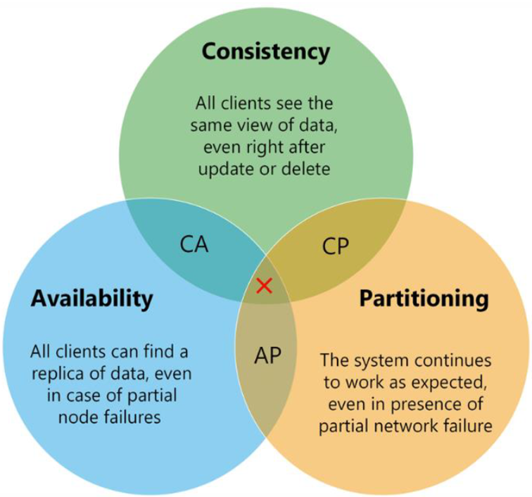
Consistency
Consistency means that if the system get any read request, the data should return last updated value from database under all circumstances. If the data cannot be retrieved, an error should be throw and if data is not up-to-date, then it should never be returned. So, when consistent not provide, the system must block the request until all replicas update.
Availability
The ability of a distributed system to respond to requests at any time. If distributed system can respond all request any time, we can say that the system has high availability. Even if one node in any cluster is down, the system should be able to survive with other nodes. Also high available systems can be fault-tolerance in order to accommodate all requests. Availability in a distributed system ensures that the system remains operational 100% of the time.
Partition Tolerance
Partition Tolerance is actually network partitioning. That means, parts of your system are located in different networks. Partition Tolerance is the ability of the system to continue its life in case of any communication problem that may occur between the nodes. Its basically guarantees the system continues to operate even if one data node is down.
Consistency and Availability at the same time ?
So now we should ask this question is it possible for a system to be both Consistency and Availability at the same time?
CAP Theorem said that If there is Partition Tolerance, either Availability or Consistency should be selected. We should sacrifice Availability or Consistency in distributed systems.
In distributed systems, it is a common way that data centers are kept in different locations, mostly on different machines and networks. For this reason, Partition Tolerance is a must for distributed architectures. Because one of the reasons for the emergence of NoSQL databases is to easily overcome the Single Point of Failure problem.
Because in relational databases mostly stored in the data center is in a single network infrastructure that creates a kind of single point of failure situation. Relational databases prevent distribute data from different nodes. For this reason, NoSQL databases don’t include foreign keys, joins, that is, relations between data.
The unrelated data allows it to be stored in a distributed manner much more easily within the different nodes of the system. This also makes NoSQL type databases easily scalable.
As a result, in this case, a distributed system doesn’t have the luxury of not providing Partition Tolerance anyway. When you look at the no-sql database systems like MongoDB, Cassandra, you can see that none of them gave up on Partition Tolerance and made a choice between Availability and Consistency.
So in a distributed architecture, Partition Tolerance seems to be a must-have feature. In this case, it is usually necessary to choose between Consistency or Availability when designing distributed systems.
If a system is to be fully consistent, it must be sacrifice that always available. Otherwise, even if it is desired to be accessible at all times, the consistency should be sacrificed. Mostly in microservices architectures choose Partition Tolerance with High Availability and follow Eventual Consistency for data consistency.
As you can see that how we can consider CAP Theorem when
designing distributed systems and understand the concepts of Consistency,
Availability, and Partition Tolerance.
41. Microservices Distributed Caching
We are going to talk about Microservices Caching. Caching is one of the important topic when you want your application faster.
Caching can increase performance, scalability, and availability for microservices. The main idea is reducing latency with cache and makes application faster. When the number of requests are increased, caching will be really important for accommodating whole requests with high availability.
If application request mostly comes for reading data that is not changes so frequently, then Caching will be so efficient. In Microservices architectures are typically implement a distributed caching architecture.
An API Gateway accommodate requests and invoke several internal backend microservices and aggregate them into 1 response.
So how we can increase the speed of this use case ?
Of Course we should use The distributed cache. The distributed
cache increases system responsiveness by returning cached data.
Additionally, separating the cache server from the
microservices, gives ability to independently scale up cache services. This can
be very useful when increased traffic of requests.
You can also use in-memory cache in our microservices, but it
is not efficiency like distributed cache due to scalability issues. So now we
can use distributed cache in our e-commerce design.

Design the Architecture — Microservices
Distributed Caching
Distributed caching is a technique used in computer systems to improve performance and scalability by storing frequently accessed data in memory across multiple servers or nodes. The goal is to reduce the number of requests to backend storage systems and improve response times.
In distributed caching, data is typically stored in key-value pairs, where a unique key is used to access the corresponding value. When a client requests data, the distributed cache first checks whether the data is already stored in memory. If it is, the data is returned directly from the cache, avoiding the need to access the backend storage system.
Distributed caching can be implemented using different architectures, such as peer-to-peer, client-server, or hybrid models. In a peer-to-peer model, each node in the system stores and serves cached data, and nodes communicate with each other to update and synchronize the data. In a client-server model, clients communicate with a dedicated server or a cluster of servers that store and manage the cached data.
Some popular distributed caching solutions include Apache Ignite, Redis, Memcached, and Hazelcast. These solutions provide features such as data partitioning, replication, eviction policies, and integration with various programming languages and frameworks.
Distributed caching can significantly improve system performance, reduce latency, and increase scalability, especially in applications with high read/write ratios or large datasets. However, it requires careful design and management to ensure consistency, reliability, and fault tolerance.
Redis
Redis, which stands for Remote Dictionary Server, is a fast, open-source, in-memory key-value data store for use as a database, cache, message broker, and queue. Redis is Fast, open source in-memory data store for use mostly as a database and cache. So its good to use Redis in our architecture.
42.
What is Service-Oriented
Architecture ?
Service-oriented architecture (SOA) is an architectural style for designing and building software applications based on the concept of services. A service is a self-contained, modular unit of functionality that can be accessed over a network using a well-defined interface. SOA aims to create a system of loosely coupled services that can be reused, combined, and orchestrated to fulfill specific business processes and requirements.
SOA is often used to design large, complex, and distributed systems that require integration with multiple platforms, applications, and data sources. The key benefits of SOA include:
- Reusability: Services can be developed, deployed, and reused across different applications and platforms, reducing development time and costs.
- Interoperability: Services can be accessed and consumed by other services regardless of the underlying technology or platform, promoting integration and interoperability.
- Flexibility: Services can be modified and updated independently, without affecting other services or the overall system, allowing for greater flexibility and agility.
- Scalability: Services can be replicated and distributed across multiple nodes or servers, allowing for horizontal scaling and improved performance.
SOA uses standards-based protocols and interfaces such as SOAP (Simple Object Access Protocol), REST (Representational State Transfer), and WSDL (Web Services Description Language) to facilitate communication between services. Services can be organized and managed using a service registry or a service bus, which provides centralized discovery, routing, and governance of services.
Some common components of SOA include service providers (which implement services), service consumers (which access services), service registries (which store information about available services), and service buses (which handle communication and routing between services).
SOA has been widely adopted in enterprise and government settings, and it has influenced the development of related architectures such as microservices and event-driven architecture.
43. Enterprise service bus
An enterprise service bus (ESB) is a middleware architecture that enables communication and integration between different applications, systems, and services within an enterprise. An ESB acts as a mediator or a hub that connects various components of the enterprise system and facilitates the exchange of data and messages.
An ESB typically provides the following features:
- Message routing and transformation: An ESB can route messages between different applications and systems based on predefined rules and policies. It can also transform messages between different formats and protocols to ensure interoperability.
- Message validation and enrichment: An ESB can validate incoming messages for syntax and semantic correctness, and enrich them with additional data and metadata to facilitate processing and analysis.
- Service orchestration: An ESB can coordinate and execute business processes by invoking multiple services and applications in a predefined sequence, and managing the interactions and dependencies between them.
- Security and governance: An ESB can provide security features such as authentication, authorization, and encryption to ensure the confidentiality, integrity, and availability of the data and services. It can also enforce policies and regulations related to data privacy, compliance, and auditing.
Some popular ESB solutions include MuleSoft Anypoint Platform, Apache ServiceMix, IBM Integration Bus, and Oracle Service Bus. These solutions provide a range of features and tools for developing, deploying, and managing ESB-based applications and systems.
ESB can be used to integrate heterogeneous systems and services across different platforms, languages, and protocols, and can provide a scalable and reliable infrastructure for mission-critical applications. However, it requires careful planning and management to ensure performance, reliability, and maintainability.
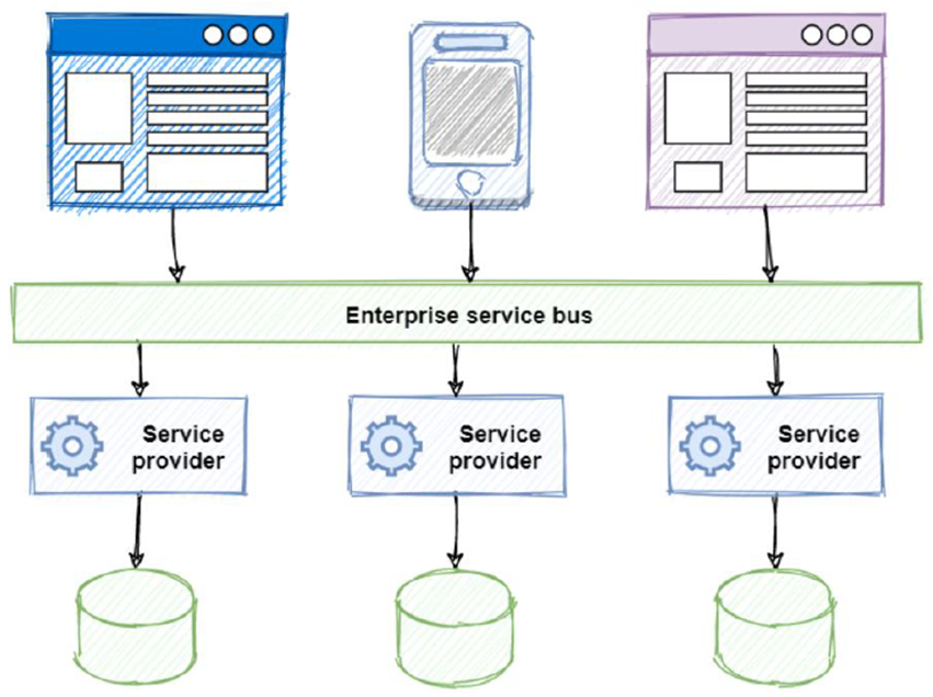
44.
The Clean Architecture
The Clean Architecture is an architectural pattern for designing software systems that prioritize modularity, maintainability, and independence from external technologies. The pattern was proposed by Robert C. Martin, also known as "Uncle Bob," in his book "Clean Architecture: A Craftsman's Guide to Software Structure and Design."
The Clean Architecture consists of several layers, each with a specific responsibility and level of abstraction. The layers are arranged in a concentric ring, with the innermost layer representing the most high-level and abstract concepts, and the outer layers representing the more concrete and implementation-specific details.
The layers of the Clean Architecture typically include:
- Entities: This layer contains the business objects and entities that encapsulate the core functionality and business rules of the system. Entities are usually language-agnostic and independent of any external technologies or frameworks.
- Use cases: This layer contains the application-specific use cases and interactions with the entities. Use cases encapsulate the application's business logic and represent the specific ways in which the entities are used.
- Interfaces: This layer defines the interfaces between the application and the external world, such as the user interface, network, and database. The interfaces are typically technology-specific and can be adapted to different platforms and frameworks.
- Infrastructure: This layer contains the external libraries, frameworks, and tools that provide the technical infrastructure for the system, such as the database access layer, the network layer, and the logging and monitoring systems.
The Clean Architecture promotes several design principles, including separation of concerns, single responsibility principle, dependency inversion principle, and open-closed principle. These principles aim to create a modular, flexible, and extensible system that can adapt to changing requirements and technologies.
The Clean Architecture can be applied to various programming paradigms, such as object-oriented, functional, and reactive programming. It can also be used in conjunction with other architectural patterns, such as microservices and event-driven architecture.

Advantages
Some advantages of using Clean Architecture are;
· Write clean, readable and interpretable code.
· Easy testability.
· Write maintainable code.
· Reducing complexity in package and class structure.
· To progress more easily, effectively and quickly in teamwork.
· It is independent of interface, database and framework.
· It avoids code duplication.
Disadvantages
· Contains lots of classes and packages. For that, it may not be very convenient for small projects that are not very complex.
· Because it is made up of layers, it may take time to understand how all layers work with each other.
· Learning without practice can be difficult.
45. Hexagonal Architecture
The Hexagonal Architecture, also known as Ports and Adapters Architecture, is a software architecture pattern that aims to make a software system flexible, maintainable, and testable. The pattern was first introduced by Alistair Cockburn and later popularized by a book written by Dr. Gernot Starke.
The Hexagonal Architecture consists of an innermost core that contains the business logic and domain entities, surrounded by layers of adapters that provide interfaces to the external world. The core is surrounded by a set of ports that define the business logic's input and output interfaces. The adapters then translate these inputs and outputs to and from the external world's protocols, such as databases, user interfaces, and web services.
The key idea behind the Hexagonal Architecture is to separate the core business logic of the system from its external interfaces and technical details.
The adapters in the architecture are responsible for translating the input and output data to and from the external systems. The adapters are also responsible for providing a way for the core to communicate with the external systems. The adapters can be swapped out or replaced without affecting the core's functionality, making the system more flexible and adaptable.
The ports in the architecture define the interfaces between the core and the adapters. The ports specify the inputs and outputs that the core expects and provides. The ports define the contract between the core and the adapters, and they allow the core to remain independent of the external systems.
At its core, the Hexagonal Architecture consists of three layers:
- The Domain layer: This layer contains the core business logic and domain objects of the system. It represents the heart of the system, and should be independent of any specific technical details or external interfaces.
- The Application layer: This layer contains the use cases and application-specific logic that define how the system interacts with external actors, such as users or other systems. The Application layer provides an interface to the Domain layer, and is responsible for coordinating the interactions between the domain objects and the external world.
- The Infrastructure layer: This layer contains the technical details and implementations that connect the system to the external world. The Infrastructure layer includes the adapters that connect the system to external technologies, such as databases, web services, or user interfaces.
The key benefit of the Hexagonal Architecture is its flexibility and modularity. By separating the core business logic from its external interfaces and technical details, the Hexagonal Architecture allows each component to be developed and tested independently, making it easier to evolve and adapt the system over time.
Another benefit of the Hexagonal Architecture is its testability. By isolating the core business logic in the Domain layer, it becomes easier to write automated tests that verify the correctness of the system. The external interfaces can be tested using their respective adapters in the Infrastructure layer, without the need to access the core business logic directly.
The Hexagonal Architecture is technology-agnostic, which means that it can be applied to different programming languages, frameworks, and platforms. This makes it a flexible and adaptable approach to software development that can be used in a wide range of contexts and projects.
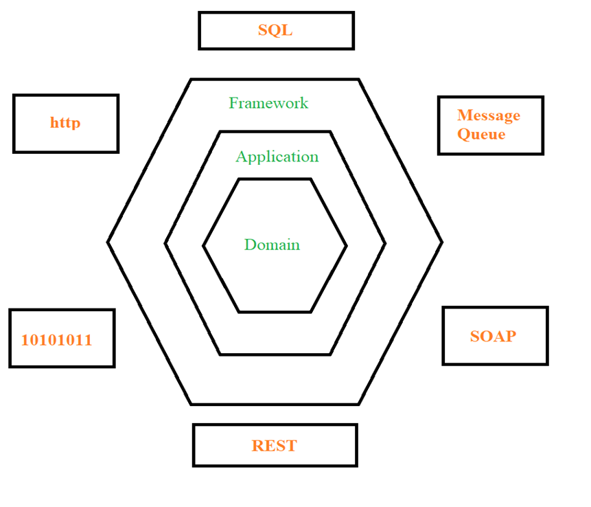
46.
The Onion Architecture (Jeffrey
Palermo)
The Onion Architecture is a software architecture pattern that aims to create a maintainable and testable software system by separating concerns and dependencies into layers that are arranged in a concentric circle pattern. The key idea behind the Onion Architecture is to place the most important and stable parts of the system in the center of the circle, and the more volatile and changeable parts towards the outside.
At its core, the Onion Architecture consists of four layers:
- The Domain layer: This layer contains the core business logic and domain objects of the system. It represents the heart of the system, and should be independent of any specific technical details or external interfaces.
- The Application layer: This layer contains the use cases and application-specific logic that define how the system interacts with external actors, such as users or other systems. The Application layer depends on the Domain layer, but is independent of any specific technical details or external interfaces.
- The Infrastructure layer: This layer contains the technical details and implementations that connect the system to the external world. The Infrastructure layer includes the adapters that connect the system to external technologies, such as databases, web services, or user interfaces. The Infrastructure layer depends on the Application layer, but should not depend on the Domain layer.
- The User Interface layer: This layer contains the user interface components and presentation logic of the system. The User Interface layer depends on the Application layer, but should not depend on the Domain layer or the Infrastructure layer.
The key benefit of the Onion Architecture is its flexibility and modularity. By separating concerns and dependencies into layers, the Onion Architecture allows each component to be developed and tested independently, making it easier to evolve and adapt the system over time. The use of interfaces between the layers also makes it easier to swap out specific implementations or technologies without affecting the rest of the system.
Another benefit of the Onion Architecture is its testability. By isolating the core business logic in the Domain layer, it becomes easier to write automated tests that verify the correctness of the system. The external interfaces can be tested using their respective adapters in the Infrastructure layer, and the application-specific logic can be tested using the Application layer.
The Onion Architecture is technology-agnostic, which means that it can be applied to different programming languages, frameworks, and platforms. This makes it a flexible and adaptable approach to software development that can be used in a wide range of contexts and projects.

47.
Screaming Architecture
Screaming Architecture is a term coined by software architect Robert C. Martin, also known as "Uncle Bob". It refers to an architectural style that emphasizes the clarity and simplicity of the system's structure, as well as its flexibility and maintainability.
The key idea behind Screaming Architecture is to design a system in a way that its architecture is immediately visible, clear, and easily understandable to developers, stakeholders, and users. The architecture should "scream" its purpose and intentions, rather than hiding them behind layers of complexity or obfuscation.
To achieve this goal, Screaming Architecture emphasizes the use of well-defined boundaries between different parts of the system, and clear separation of concerns. Each component should have a clear and well-defined responsibility, and should be structured in a way that makes its purpose and dependencies immediately clear.
Screaming Architecture is often associated with the use of Domain-Driven Design (DDD), which emphasizes the importance of modeling the business domain of the system in a way that is clear and easily understandable to all stakeholders. In a Screaming Architecture system, the domain model should be the core of the system, and should be structured in a way that makes its purpose and behavior clear.
Another key aspect of Screaming Architecture is its emphasis on flexibility and adaptability. A Screaming Architecture system should be designed in a way that allows it to evolve and adapt to changing requirements and business needs. This requires a modular and flexible architecture that can be easily modified and extended without affecting the rest of the system.
Overall, Screaming Architecture is a software design philosophy that emphasizes clarity, simplicity, and flexibility. By making the architecture of a system immediately visible and clear, it can help to improve the maintainability, flexibility, and overall quality of software systems.
48.
What is N-Layer architecture ?
The number of layers in an N-Layer architecture can vary depending on the complexity and requirements of the system. However, the most common implementation consists of the following layers:
- Presentation Layer: This layer is responsible for presenting the user interface and handling user input. It interacts with the business layer to execute operations and retrieve data.
- Application Layer: This layer contains the application logic and business rules. It receives input from the presentation layer, performs business logic, and coordinates data access and manipulation from the data layer.
- Domain Layer: This layer contains the business domain objects and logic. It represents the core of the application and is responsible for encapsulating the business rules and behaviors.
- Data Layer: This layer contains the data access logic and infrastructure. It interacts with the domain layer to retrieve and persist data.
Each layer in the N-Layer architecture depends only on the layer below it. This separation of concerns and dependencies allows each layer to be developed, tested, and maintained independently. It also enables the system to be more flexible and adaptable to changes, as modifications in one layer do not affect the others.
One of the main benefits of the N-Layer architecture is its modularity, which makes it easier to maintain and extend the system. It also enables developers to easily test each layer in isolation, which can improve the overall quality and reliability of the software system.
However, implementing an N-Layer architecture can also increase the complexity of the system, as well as the development time and effort. It is important to carefully consider the needs and requirements of the system before deciding to use this pattern.
49.
Design principles — Separation of
Concerns (SoC)
Separation of Concerns is a fundamental design principle in software engineering that aims to separate different concerns or aspects of a software system into distinct and independent parts. The goal of this principle is to make the system more modular, flexible, and easier to maintain.
In software design, a concern is a particular aspect or feature of the system, such as user interface, data persistence, security, or business logic. By separating concerns, we can minimize the interactions and dependencies between different parts of the system, which can reduce complexity and improve the system's overall quality and maintainability.
There are several ways to achieve separation of concerns, including:
- Modularization: Breaking down the system into smaller, self-contained modules, each responsible for a specific concern.
- Layering: Separating the system into different layers, each with a specific responsibility and communicating with adjacent layers through well-defined interfaces.
- Aspect-Oriented Programming (AOP): Separating the concerns that crosscut multiple modules and encapsulating them in aspects.
- Design Patterns: Using well-established patterns to separate concerns, such as the Model-View-Controller (MVC) pattern for separating the user interface from the business logic.
By separating concerns, we can also improve the system's scalability and extensibility, as each module or layer can be developed, tested, and maintained independently. It can also help in reducing the risk of system failures, as the separation of concerns can help in identifying and isolating errors to a specific module or layer.
Overall, Separation of Concerns is a key design principle that helps in creating modular, maintainable, and high-quality software systems.
50. Client-server pattern
The client-server pattern is a popular distributed computing model in which a client process requests services or resources from a server process over a network. In this pattern, the server provides a service or resource to the client in response to a request made by the client. The client and server processes can be running on different machines and communicate over a network.
The basic workflow of the client-server pattern is as follows:
- The client process sends a request to the server process over the network.
- The server process receives the request and processes it.
- The server process sends a response back to the client process over the network.
- The client process receives the response and processes it.
The client-server pattern is widely used in many applications, such as web applications, email systems, and file transfer protocols. This pattern allows for scalable and efficient communication between distributed systems, as well as enabling the separation of concerns between client and server code.

Usage
Online applications such as email, document sharing and
banking.
51. Master-slave pattern
This pattern consists of two parties; master and slaves. The
master component distributes the work among identical slave components, and
computes a final result from the results which the slaves return.
Usage
· In
database replication, the master database is regarded as the authoritative
source, and the slave databases are synchronized to it.
· Peripherals
connected to a bus in a computer system (master and slave drives).
52. Pipe-filter pattern
This pattern can be used to structure systems which produce
and process a stream of data. Each processing step is enclosed within a filter
component. Data to be processed is passed through pipes. These pipes can be
used for buffering or for synchronization purposes.

Usage
· Compilers.
The consecutive filters perform lexical analysis, parsing, semantic analysis,
and code generation.
· Workflows
in bioinformatics.
53. Broker pattern
This pattern is used to structure distributed systems with
decoupled components. These components can interact with each other by remote
service invocations. A broker component is responsible for the coordination of
communication among components.
Servers publish their capabilities (services and
characteristics) to a broker. Clients request a service from the broker, and
the broker then redirects the client to a suitable service from its registry.

Usage
· Message
broker software such as Apache ActiveMQ, Apache Kafka, RabbitMQ and JBoss
Messaging.
54. Peer-to-peer pattern
In this pattern, individual components are known as peers.
Peers may function both as a client, requesting services from other peers, and
as a server, providing services to other peers. A peer may act as a client or
as a server or as both, and it can change its role dynamically with time.
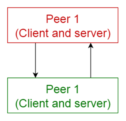
Usage
· File-sharing
networks such as Gnutella and G2)
· Multimedia
protocols such as P2PTV and PDTP.
· Cryptocurrency-based
products such as Bitcoin and Blockchain
55. Event-bus pattern
This pattern primarily deals with events and has 4 major
components; event source, event listener, channel and event bus. Sources
publish messages to particular channels on an event bus. Listeners subscribe to
particular channels. Listeners are notified of messages that are published to a
channel to which they have subscribed before.

Usage
· Android
development
· Notification
services
56. Model-view-controller pattern
This pattern, also known as MVC pattern, divides an
interactive application in to 3 parts as,
model — contains the core
functionality and data
view — displays the information to
the user (more than one view may be defined)
controller — handles the input from the
user
This is done to separate internal representations of
information from the ways information is presented to, and accepted from, the
user. It decouples components and allows efficient code reuse.

Usage
· Architecture
for World Wide Web applications in major programming languages.
· Web
frameworks such as Django and Rails.
57. Blackboard pattern
This pattern is useful for problems for which no deterministic
solution strategies are known. The blackboard pattern consists of 3 main
components.
blackboard — a structured global memory
containing objects from the solution space
knowledge source — specialized modules
with their own representation
control component —
selects, configures and executes modules.
All the components have access to the blackboard. Components
may produce new data objects that are added to the blackboard. Components look
for particular kinds of data on the blackboard, and may find these by pattern
matching with the existing knowledge source.

Usage
· Speech
recognition
· Vehicle
identification and tracking
· Protein
structure identification
· Sonar
signals interpretation.
58. Interpreter pattern
This pattern is used for designing a component that interprets
programs written in a dedicated language. It mainly specifies how to evaluate
lines of programs, known as sentences or expressions written in a particular
language. The basic idea is to have a class for each symbol of the language.

Usage
· Database
query languages such as SQL.
· Languages
used to describe communication protocols.
Comparison of Architectural Patterns
The table given below summarizes the pros and cons of each
architectural pattern.

59.
MVC Pattern
In the MVC pattern, features are divided into three components
based on three separate concerns. Firstly, the view is responsible for
rendering UI elements. Secondly, the controller responds to UI actions. And the
model handles business behaviors and state management.
In most implementations, all three components can directly
interact with each other. However, in some implementations, the controller is
responsible for determining which view to display.
The diagram below shows the MVC flow of control:
The model represents the whole business logic layer. The view
represents the data fetched from the model. In addition, it handles
presentation logic. Lastly, the controller handles control flow logic and
updates the model.
MVC doesn't specify how the view and the model should be
structured internally. Usually, the view layer is implemented in a single
class.
However, in that case, a couple of problems can arise:
· The view
and the model are tightly coupled. As a result, feature requirements of the
view can easily drip down to the model and pollute the business logic layer
· The view
is monolithic and usually couples tightly with the UI framework. Thus, unit
testing the view becomes difficult
60.
MVP Pattern
The MVP pattern is a UI presentation pattern based on the
concepts of the MVC pattern. However, it doesn't specify how to structure the
whole system. It only dictates how to structure the view.
This pattern separates responsibilities across four components
in general. Firstly the view is responsible for rendering UI elements.
Secondly, the view interface is used to loosely couple the presenter from its
view.
Finally, the presenter interacts with the view and model, and
the model is responsible for business behaviors and state management.
In some implementations, the presenter interacts with a
service (controller) layer to retrieve/persist the model. The view interface
and service layer are commonly used to make writing unit tests for the
presenter and the model easier.
The diagram below shows the MVP flow of control:

The model is the same as in MVC and contains the business
logic. The view is a passive interface that displays data. It sends user
actions to the presenter.
The presenter sits between the model and view. It triggers
business logic and enables the view to update. It receives data from the model
and shows the same in the view. This makes testing the presenter much easier.
Still, there are some problems with MVP:
· The
controller is often omitted. Because of the lack of a controller, control flow
has also to be handled by the presenter. This makes the presenter responsible
for two concerns: updating the model and presenting the model
· We can't
utilize data binding. If binding is possible with the UI framework, we should
utilize it to simplify the presenter
61.
Comparison Between MVC and MVP
There aren't a whole lot of differences between MVC and MVP.
Both patterns focus on separating responsibility across multiple components,
hence, promoting loose coupling of the UI (View) from the business layer
(Model).
|
|
MVC |
MVP |
|
Coupling |
The view and the model
are tightly coupled in MVC |
loosely
coupled in MVP |
|
Communication |
The controller and view
layer falls in the same activity/fragment in MVC |
In MVP, communication
between the View-Presenter and Presenter-Model happens via an interface. |
|
User Input |
In MVC, user inputs are
handled by the Controller that instructs the model for further operations. |
In MVP,
user inputs are handled by the view that instructs the presenter to call
appropriate functions |
|
Type of Relation |
A many-to-one
relationship exists between the controller and view. One Controller can
select different views based upon required operations in MVC. |
The presenter and view have a one-to-one relationship in
MVP, where one presenter class manages one view at a time
|
|
Main Component |
In MVC, the controller
is in charge. It creates the appropriate view and interacts with the model
according to the user’s request |
In MVP, the view is in charge. The view call methods on the
presenter, which further directs the model
|
|
Unit Testing |
Due to tight coupling,
MVC has limited support for unit testing |
unit Testing is well
supported in MVP |
62.
MVVM Architecture
This software architecture pattern helps us to address the
Separation of Concern. It separates the GUI design from the application's
backend, making it loosely coupled. It is used mostly in developing client
applications. Let's understand each component of MVVM.
Model
The model represents the domain model also considered as
Business Logic / Data Access Logic or we can abstractly define it as the
backend of the application. They hold application data.
View
View Represents the UI of the application. This is what the
user interacts with. It is the presentation part.
ViewModel
It is the logic of View. The ViewModel is also called as
presentation logic. The View and ViewModel communicate with each other. The
Request from ViewModel is forwarded to Model / Business Logic Layer / Data
Access Layer. It allows sharing of computed/resultant data to the view.
63. What is the difference between Factory and Strategy patterns?
A factory pattern is a creational pattern. A strategy pattern
is an operational pattern. Put another way, a factory pattern is used to create
objects of a specific type. A strategy pattern is use to perform an operation
(or set of operations) in a particular manner. In the classic example, a
factory might create different types of Animals: Dog, Cat, Tiger, while a
strategy pattern would perform particular actions, for example, Move; using
Run, Walk, or Lope strategies.
The strategy pattern allows you to polymorphically change
behavior of a class.
The factory pattern allows you to encapsulate object creation.
No comments:
Post a Comment